

Table of contents
Table of contents
You are a beginner with NULA boards. Or electronics? A specific module caught your eye, but you do not know how to use it? Do not worry, HUM is here for you! How to Use Module (HUM) is a blog tutorials series by soldered where you will find all you need in order to begin working with your favorite module. Tutorials include: technical characteristics, work principle, instructions on how to connect module with NULA board and the basic code. Everything else is left to your imagination.
INTRODUCTION
You have certainly already encountered some type of a DC motor. You know that connecting the DC motor’s pins to a source of certain voltage results in rotating the motor to one side. Also, if we switch pins on the motor and connect the power source the opposite way, we will see that the motor rotates to the opposite side. This feature of the motor is very useful, but it is complicated to constantly switch pins of the motor manually. There must be an electronic circuit which can do it for us? Of course there is. The answer is in the H-bridge circuit. Using it, we can easily and safely change the motor rotation direction. In continuation, we will explain the H-bridge work principle in more detail.

Characteristics:
• Maximum current: up to 4 A peak / 2.5 A full-scale per bridge
• Maximum voltage: 33 V
• Dual H-bridge based on the DRV8424P driver (drives two DC motors independently)
• Control via PWM inputs AIN1 and AIN2 (Bridge A) and BIN1 and BIN2 (Bridge B)
HOW DOES IT WORK?
H-bridge is a circuit that, in theory, consists of four switches connected to some load (e.g. DC motor). Various configurations of these switches can allow us to control current flow in the circuit. Using the H-bridge, it is very simple to switch the polarity on the load. Even though the load can theoretically be whatever you want, by far, the most widely used H-bridge application is for DC and stepper motors.


It is most commonly used to control and replace the DC motor rotation direction. H-bridge is also used in many other applications such as DC/AC, AC/AC or DC/DC converters. The H-bridge circuit reminds of the letter H, and that is how it has gotten its name.
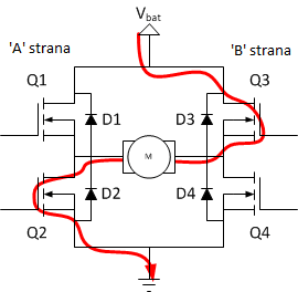
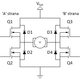 The image above represents a scheme display of the H-bridge. We can see that the H-bridge consists of four MOSFETs connected in a certain way. Because of the inability to simultaneously switch between the two possible states of the bridge, diodes were added to the circuit in order for it to ensure simultaneous switch of states and limit the current’s flow power during these short periods of imbedding, without the load voltage being too high. The upper end of the bridge is connected to a power source (e.g. battery), while the bottom end is grounded. The basic work principle of the H-bridge is very simple: if Q1 and Q4 are turned on, the left cable of the motor will be connected to the power supply, and the right to the ground. The current flows through the motor (so to say) in the forward direction, and the engine shaft starts rotating.
 If Q2 and Q3 are on, what will happen is quite the opposite, the motor is powered in the reversed direction, and the shaft will rotate in the opposite direction.
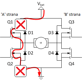
 You must never close Q1 and Q2 (or Q3 and Q4) at the same time! If that happens, a direct path between the power supply voltage and ground which is of very low resistance is created, which ultimately results in a short circuit. A short circuit can lead to destruction of the H-bridge, or some other component in the circuit.
 The table below shows every possible combination of switch states and their outcome.
It is necessary to note that this module uses the DRV8424P driver IC, which integrates two full H-bridges (Bridge A and Bridge B) built from N-channel power MOSFETs, so it can drive two DC motors independently. Each bridge is controlled by two PWM input pins: AIN1 and AIN2 for Bridge A, and BIN1 and BIN2 for Bridge B. The driver handles all the switching internally, including dead-time and shoot-through protection, so you do not have to look out for accidentally making a short circuit or destroying the module. On top of that, it provides built-in protection such as overcurrent, undervoltage and overtemperature shutdown, and reports faults on the FAULT pin (more about MOSFETs here).
HOW TO CONNECT IT?
Below, we will show the connection of the H-bridge module with the DC motor whom we will control using NULA DeepSleep.


H-bridge contains several pins:
VCC - Input for the external power supply (0-33 V).
GND - Serves for connecting minuses of the power supply.
AIN1, AIN2 - PWM control pins for Bridge A.
BIN1, BIN2 - PWM control pins for Bridge B.
SLEEP - Puts the driver into low-power sleep mode when pulled LOW (pulled HIGH / active by default).
FAULT - Fault indicator output; goes LOW when the driver reports a fault (overcurrent, overtemperature, undervoltage).
AOUT1, AOUT2 - Outputs for the first DC motor (Bridge A).
BOUT1, BOUT2 - Outputs for the second DC motor (Bridge B).
The image below shows an example of the correct connection of the H-bridge with the NULA board. It is necessary to note that the AIN1 and AIN2 module pins are connected to the NULA board, while the DC motor is connected to the AOUT1 and AOUT2 pins. It is not important which output pin (AOUT1 or AOUT2) is connected to which DC motor connector, as the rotation direction will be determined in the program.

ARDUINO CODE
There is no need to use any library for motor control using the H-bridge module. By simply switching the AIN1 and AIN2 inputs on/off using the digitalWrite() function, we start the motor. The motor will rotate only when the AIN1 pin’s state is different from the AIN2 pin’s state. When their states are the same (AIN1=AIN2), both motor connectors are at the same voltage and the motor does not rotate. Therefore, when the AIN1 pin is in HIGH state, and AIN2 in LOW, the motor will rotate in one direction. When the AIN1 pin is in LOW state, and AIN2 pin in HIGH, the motor will rotate to the opposite direction. The SLEEP pin is pulled HIGH on the board, so the driver is active by default and you do not need to drive it in code (pull it LOW only if you want to enter low-power mode).


