

If you have ever connected a sensor, a display or a breakout board to an Arduino, an ESP32 or a Raspberry Pi, you have seen the letters I2C.
At first it looks like a lot to take in. There are pins called SDA and SCL, every device has an address, and several modules share the same two wires. The underlying idea is small, though, and once it clicks the rest of the protocol follows from it.
I2C lets one board talk to sensors, displays, clocks, memory chips and IO expanders over two signal wires. You do not give each module its own set of pins. They all sit on the same pair, and the board picks which one it is talking to by name.
What is I2C?
I2C stands for Inter-Integrated Circuit, sometimes written I²C. It is a communication protocol that lets chips on the same board, or modules on the end of a cable, exchange data over two shared wires.
In a maker project the controller is an Arduino, an ESP32, a Raspberry Pi or another development board. The devices on the other end are sensors, displays, real-time clocks, EEPROMs, ADCs and IO expanders.
The reason it is everywhere is wiring. A four-line SPI display plus a four-line SPI sensor costs you eight pins. Both of those parts on I2C cost you two, and the third and fourth device cost you nothing extra. On a board with fifteen usable pins, that difference decides what you can build.


What do SDA and SCL mean?
I2C uses two signal lines, and every device on the bus connects to both.
SDA is Serial Data. It carries the actual information, one bit at a time, in both directions.
SCL is Serial Clock. It carries the timing. The controller drives it, and every bit on SDA is read on a clock edge, so all the devices stay in step.
SDA carries the message and SCL sets the rhythm. Both lines also need power and ground alongside them, which is why an I2C connection is four wires in practice even though only two of them carry signal.
How does I2C communication work?
A single exchange follows the same five steps every time:
- The controller pulls SDA low while SCL is still high. That is the start condition, and it tells every device on the bus to pay attention.
- The controller sends the address of the device it wants, plus one bit saying whether it intends to read or write.
- The device with that address answers with an acknowledge bit. The rest go back to ignoring the bus.
- Data bytes move in whichever direction the controller asked for, each one acknowledged.
- The controller releases SDA while SCL is high. That is the stop condition, and the bus is free again.

Nothing on the bus speaks unless it is spoken to. That is the whole trick behind sharing two wires between a dozen parts.
What is an I2C address?
An I2C address is the device's name on the bus. Standard I2C uses 7 bits, so there are 128 possible addresses, and a handful of those are reserved. The address is set by the chip manufacturer, and it is printed in the datasheet as a hex number such as 0x27 or 0x51.
Most chips let you change part of the address, usually the bottom two or three bits, with solder jumpers or an address pin. The 16x2 I2C LCD is a clear example: the top four bits are fixed at 0100 and the A2, A1 and A0 jumpers pick the rest.
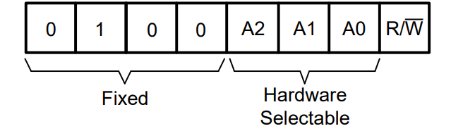
Two devices with the same address on the same bus is the failure you will hit sooner or later. Both answer at once, the data comes back as garbage, and nothing about the wiring looks wrong. The fix is to change one address with the jumpers, or to split the parts across two buses.
When a project stops responding, run an I2C scanner sketch first. It walks all 128 addresses and prints what answers. If your sensor is not in the list, the problem is power or wiring, not your code.


Why I2C is useful for Arduino and ESP32 projects
The practical benefits stack up fast:
- Two pins for the whole bus, however many devices hang off it.
- Adding a module is a wiring change of zero pins and a couple of lines of code.
- Almost every sensor and display worth using has a maintained Arduino library.
- It works over a cable, so the sensor can sit away from the board.
- It suits small builds, where you run out of pins long before you run out of space.
An IO expander is the clearest illustration. It is an I2C chip whose whole job is to give you more pins, so two pins on your board turn into sixteen on the expander. Buttons, LEDs and relays that would have eaten your GPIO all move onto the bus.


Why Qwiic connectors make I2C easier
Plain I2C wiring means four jumper wires per module: SDA, SCL, power and ground. Get one of them crossed and the module is silent, or worse, warm. Multiply that by four sensors on a breadboard and most of your debugging is wiring, not code.
Qwiic replaces those four wires with one keyed four-pin cable. It only fits one way round, the pin order is fixed across every board that uses it, and the connectors daisy-chain, so the second sensor plugs into the first rather than back into the board.
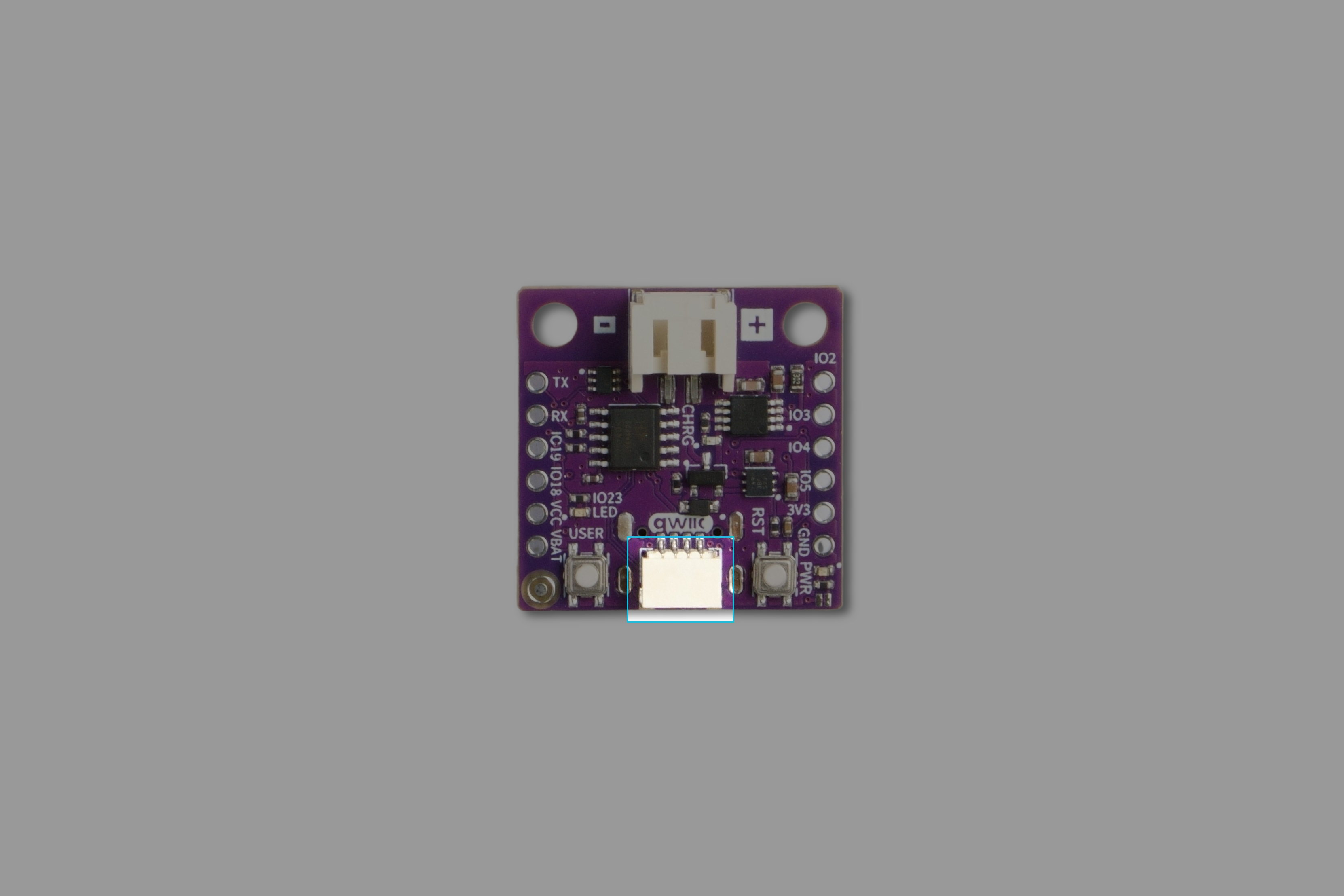
None of this changes the protocol. The same two signals run through the same two conductors, and a Qwiic sensor and a jumper-wired one look identical to your code. What changes is how many ways there are to get it wrong. Every Soldered breakout has the connector, and the Qwiic ecosystem guide covers what else is in it.


I2C with Arduino, ESP32, and Raspberry Pi
All three read the same I2C parts. What changes is the pins, the voltage and the software around it. If you are still choosing between them, Arduino vs Raspberry Pi vs ESP32 goes through the trade-offs.
I2C with Arduino
Arduino boards handle I2C through the built-in Wire library. On an Uno or any other ATmega328 board the pins are fixed: A4 is SDA and A5 is SCL. Call Wire.begin() in setup and the device library does the rest.
Two mistakes account for most beginner problems. The first is wiring to the wrong pins, because I2C is not on the pins marked SDA and SCL on every board variant. The second is leaving the address at the library default when your module ships with a different one.

I2C with ESP32
ESP32 pin assignment is flexible. Most cores default to GPIO 21 for SDA and GPIO 22 for SCL, but you can pass your own pair to Wire.begin(sda, scl) and route the bus wherever the layout needs it. Newer chips such as the ESP32-C6 use different defaults, so check the board pinout rather than copying a tutorial.
The reason to reach for an ESP32 is what happens after the reading. Wi-Fi is on the chip, so a sensor value can go straight to Home Assistant, an MQTT broker or a web dashboard. Our ESP32 projects for beginners roundup has working examples of that.
ESP32 pins are 3.3 V. Most I2C breakouts run happily at either voltage, but a 5 V module on a 3.3 V board needs checking before you plug it in.


I2C with Raspberry Pi
On a Raspberry Pi, I2C is off by default. Enable it in raspi-config, then i2cdetect -y 1 lists everything on the bus, which is the same job an Arduino scanner sketch does. SDA is on physical pin 3 and SCL on pin 5.
A Pi is worth it when the readings need somewhere to live. It runs a database, a Grafana dashboard or a local server alongside the sensor loop, which a microcontroller cannot do. Pi GPIO is 3.3 V only, with no tolerance for 5 V, so this is the platform where logic levels actually matter.


I2C vs SPI vs UART
| Protocol | Wires | Typical speed | Best for | Main advantage |
|---|---|---|---|---|
| I2C | 2 signal wires, shared | 100 kHz to 400 kHz | Sensors, character and small graphic displays, RTC modules, IO expanders | Many devices on the same two pins |
| SPI | 4 wires, plus one chip select per device | Several MHz and up | Colour displays, SD cards, flash memory, high-rate sensors | Much faster |
| UART | 2 signal wires, point to point | 9600 to 115200 baud typically | GPS modules, radios, board-to-board links | No addressing and no clock line to get wrong |
Pick I2C when you have several slow devices and few free pins. Pick SPI when one device needs to move a lot of data, such as a colour display refreshing a frame. Pick UART when exactly two things need to exchange a stream of bytes, which is why almost every GPS module uses it.
What are pull-up resistors in I2C?
I2C devices never drive their lines high. They can only pull them low or let go, which is what makes it safe for a dozen chips to share a wire: two of them talking at once cannot short a supply into a ground. Something has to bring the line back up, and that is the pull-up resistor.
Most breakout boards include their own pull-ups, so a first project usually works without you adding anything. The catch arrives with the fourth or fifth module: those resistors sit in parallel, and enough of them in parallel drag the bus down until nothing can release a line properly. Boards that expect this put the pull-ups on solder jumpers so you can cut them.
When an I2C project turns unreliable, work through pull-ups, cable length, supply voltage and duplicate addresses in that order. Long runs are the other common cause: past a metre or so the capacitance of the cable rounds off the edges, and readings start dropping out. A bus extender fixes that properly rather than by lowering the clock and hoping.


Common I2C devices and modules
| Module type | What it does | Example project |
|---|---|---|
| Temperature and humidity sensor | Measures air temperature and moisture | Weather station |
| RTC module | Keeps accurate time through power cuts | Digital clock or data logger |
| LCD display | Shows text and values | Sensor dashboard |
| IO expander | Adds sixteen input and output pins | Button panel or relay control |
| Light sensor | Measures brightness | Auto-dimming display |
| Air quality sensor | Measures CO₂ or volatile organic compounds | Room comfort monitor |
| Touch controller | Turns a surface into an input | Smart control panel |
| E-paper display | Shows information without drawing power to hold it | Calendar or dashboard |
The last row is worth a note. The e-paper panel itself is not an I2C device, but the touch controller, the RTC and the sensors around it are, which is how an e-paper display ends up as the front end of an I2C project.
Beginner I2C project ideas
1. I2C LCD temperature display
Read a temperature sensor and print the value to a 16x2 LCD. The sensor does not have to be I2C for this to work, and the DS18B20 is one-wire, but the display saves you six pins over a parallel LCD. It is the shortest path from a number in the serial monitor to a number on a screen.


2. Real-time clock project
Build a clock, or add timestamps to a data logger. Anything built on millis() drifts by minutes a day and restarts from zero after a power cut, so a log without an RTC has no usable times in it.
3. ESP32 smart home sensor
Put one or more I2C sensors on an ESP32 and publish the readings to Home Assistant or an MQTT broker. This is the project where the two-wire bus pays off, because adding a second and third sensor changes the wiring not at all.
4. IO expander button panel
Wire eight buttons and eight LEDs to an expander instead of to the board. Two pins carry the lot, and the code reads a register rather than sixteen inputs.
5. E-paper sensor dashboard
Collect temperature, humidity, air quality and time over I2C and draw the lot on an Inkplate. E-paper suits it because the panel only draws power when the image changes, so the numbers can sit on a wall for months. If Home Assistant is already running in your house, e-paper displays for Home Assistant dashboards covers that setup.


Why Soldered is a good place to start building I2C projects
I2C is worth learning early because it turns up in nearly every project past the blinking LED. Once SDA, SCL, addresses and the shared bus make sense, a datasheet stops being a wall of text and becomes a list of registers you can read.
Soldered sells the boards, sensors, displays and kits for that, built to work together. Every breakout has a Qwiic connector and a maintained Arduino library, so a new sensor is one cable and an example sketch. Start with an RTC or an LCD, add a sensor when you want something to measure, and put an Inkplate in front of it when someone other than you needs to read the numbers.
Frequently asked questions
What is I2C?
I2C is a communication protocol that lets devices talk over two shared signal wires, SDA and SCL. It is used for sensors, displays, RTC modules, IO expanders and most breakout boards.
What does I2C stand for?
Inter-Integrated Circuit. It is also written I²C, and pronounced either "eye squared see" or "eye two see".
What are SDA and SCL?
SDA is Serial Data and carries the information. SCL is Serial Clock and sets the timing, so every device reads each bit at the same moment.
How does I2C work?
The controller sends a start condition, then the address of the device it wants. Only the device with that address answers. Data moves in either direction, and a stop condition frees the bus for the next exchange.
What is an I2C address?
A 7-bit identifier that tells one device on the bus to respond and the rest to stay quiet. It is set by the chip manufacturer, and most modules let you change the lowest bits with jumpers so you can run several of the same part.
Can Arduino use I2C?
Yes, through the Wire library. On an Uno the pins are A4 for SDA and A5 for SCL.
Can ESP32 use I2C?
Yes, and the pins are configurable. Most cores default to GPIO 21 and GPIO 22, but you can pass your own pair to Wire.begin().
Can Raspberry Pi use I2C?
Yes, once you enable it in raspi-config. Use i2cdetect -y 1 to list what is connected.
What is the difference between I2C and SPI?
I2C uses two shared wires and addresses to pick a device. SPI uses four wires plus a chip select line per device, and is several times faster. I2C suits sensors and small displays, SPI suits colour displays and memory.
What is the difference between I2C and UART?
I2C is a bus with addressing, so one controller can reach many devices. UART is a point-to-point link between exactly two devices, with no addressing and no shared clock.
Why does I2C need pull-up resistors?
I2C devices can only pull a line low, never drive it high, so a resistor has to return it to the idle state. Most breakouts include their own, but with several modules on one bus the parallel resistance can get low enough to cause trouble.
How many devices can I connect to one I2C bus?
In theory 112 usable addresses, and in practice you run out of something else first. The real limits are duplicate addresses and total cable capacitance, not the address space.
What projects can I build with I2C?
Temperature displays, clocks, data loggers, smart home sensors, weather stations, button panels, e-paper dashboards and sensor monitoring systems.


